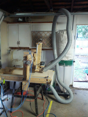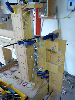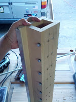
In making my mill, the Z axis and its rigidity was a key concern and so the arm that goes up and down is made of boxed 3/4" MDF and a ton of barrel nuts. These nuts seemed like a good idea initially because they are simple to work with, however the high cost (about $0.50 each!) rapidly became unbearable.
I wanted more than just a few inches of Z travel and aimed for an initial 24 inch Z arm. This translated into only about ten inches of usable travel, so I'm glad I didn't skimp. However MDF is really heavy as a material and so the weight of the Z arm hanging off the X axis gantry has caused plenty of flexing.
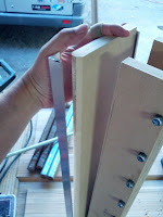
I did make use of the clever (i.e., not invented by me) skate-bearing based linear bearing mechanism. It uses skate bearings mounted in angle aluminium to create a very stable slide, however it is time consuming to create. You have to bevel the edges of your material and then accurately drill mounting holes for the bearings.
After cutting them for the Z axis I decided to do the remaining axes using specialized v-groove bearings riding on the edge of angled aluminum. This had its own problems I'll talk about below.
v.1. of the mill is constructed entirely of rectangular pieces. This is because I was able to make quick, accurate cuts on my cheap table saw. A friend brought over his bench-top drill press and we used that to plunge most of the barrel nut holes. The rest of the holes were drilled using my cordless drill. Once assembly began, however, the relative unimportance of precise 90-degree holes for barrel became apparent and so much of the drilling from there on was done with hand drills.
If you look at the side-view below of v.1 of the mill you can see the Z axis leaning forward. Correcting that lean was a major goal of v.2 of the mill. Because the uprights were cut by hand and were rectangular, this put a large amount of weight on the 'front-top' bearing and much of the time the rear-top bearing was lifted free of the rail.
Also problematic was DUST. Dust EVERYWHERE. OMG SO MUCH DUST. Once I began running the mill the amount of dust became quite overwhelming. Therefore I moved up the priority of effective dust control on the list. Also noise. The router is very loud and so hearing protection was important just to avoid ear fatigue. Babysitting the mill was a full-time and attention activity so you couldn't go far.
I purchased quality but not-too-fancy ear muffs and took to wearing my earbud headphones under them to listen to some music while holding the vacuum hose.
Another problem was the ease with which the mill could be told to overrun its axes. On several occasions I had to hit the reset button on the grbl controller to halt the mill while it bored into the spoil board. Frustrating, but limit switches and self-homing are a future feature. Having actual blocks to stop the mill from riding off the end of the rails is a good idea. I often used clamps to hold the mill components in place and act as stops.
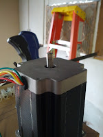
Thankfully that motor is dual-shafted and I only use the mount end to drive the Z axis. All told, however, this crappy mill was able to perform basic cuts. Once I did get the grbl controller wired up to the motor controllers and a laptop using some terminal software to send Gcode to it, I was able to make cuts.
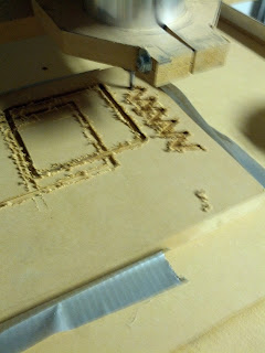
These videos show my first attempts using the cheap HSS bits that came with my router.
They sucked
They burned the wood, tore up the surface and otherwise produced crap cuts.
So I went and splurged for a $20 1/4" carbide bit.
The difference was quite remarkable.
So, at this point I had a mill that could cut random bits of Gcode I sent it. That marked the finish point of v.1 of the mill. The plan at this point was to use this crappy mill to cut upgraded parts for itself. I enlisted my son to help catch dust during these cutting exercises. I try to include my kids in my maker activities. I'll talk more about that another time.
Here's a random pic of my cousins who were in town for two days and I put to work cutting parts for v.1:
